SEMI TRAILER USER'S MANUAL - ALURA TRAILER
Brake system;
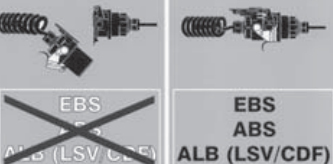
Alura semitrailers are fitted with the Electronic Brake System EBS as standard equipment
** The EBS system also includes the ABS function (Antiskid Braking System) and the ALB function (automatic load sensing braking pressure regulation)
All supply lines are combined at the front wall. The following types of coupling heads may be installed:
Standard coupling heads (production) with integrated line filters
** Different types of coupling heads can be installed simultaneously for specialised applications.
Standard coupling heads;
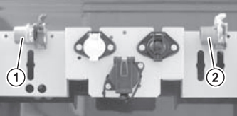
1 - Supply coupling head
2 - Brake coupling head
Connecting to the tractor
The parking brake of the tractor must be set.
· Check sealing surfaces of the coupling heads and clean if necessary.
· Always connect the brake coupling head (2) first.
o The semitrailer is braked.
· Connect the supply coupling head (1).
· Check coupling heads for leaks and replace leaking rubber seals.
Disconnecting from the tractor
· The parking brake of the tractor is set.
· Always disconnect the supply coupling head (1) first.
o The semitrailer is braked.
· Disconnect the brake coupling head (2).
· Close dust caps of coupling heads.
Vehicles built from 2002 have an additional power supply for the EBS system. This is supplied by the 7-pin socket of the lighting system. This means that the ABS and ALB will still operate even if the ABS/EBS plug connector is disconnected. The power supply through the 7-pin socket is only provided as a supplementary power supply in the event of a fault in the ABS/EBS plug connector
The "EBS" warning sign is part of the operating manual. Observe the sticker and keep it readable. Replace the "EBS" warning sticker if it is lost or becomes illegible
The EBS and thus the ABS and the automatic load sensing brake control will not operate without the ABS/EBS plug connector. This can cause the semitrailer to overbrake and skid and may result in accidents.
· Always connect the ABS/EBS plug connector between the tractor and semitrailer.
· Use only approved ABS/EBS plug connectors registered in the vehicle registration
Electrical connections;
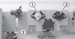
1 - 7 pin socket
2 - 15 pin socket
3 - 7 pin socket
7-pin sockets as standard equipment in accordance with ISO 1185 and 3731 (1 and 3). The 15-pin socket (2) as per ISO 12098 is available as optional equipment.
Brake/air suspension controls;
The operating console (1) is installed on the left side of the semitrailer
Compressed air tank;
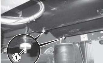
1 - Drain valve
Condensation in the compressed air reservoir may cause brakes to freeze and failure of the brake system!
· Check the drain valve of the compressed air reservoir for condensation regularly, particularly during cold weather.
· Drain any condensation completely
AIR SUSPENSION;
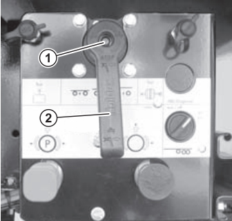
Operating console
1 - Up/down valve
2 - Selector lever (shown in "DRIVE" position)
The operating console is installed on the left side of the semitrailer
In “Drive” position the air suspension continuously maintains the driving level at the same height regardless of the load.
After changing the height for loading or unloading the basic level is reset.
You can lift and lower the level of the parked semitrailer with the up and down valve (1), e. g. for coupling and uncoupling or to adjust the height for a ramp.
If the up/down valve is not in "FAHRT" (DRIVE) position during loading or unloading, the level of the semitrailer will change as the load changes!
The up and down valve returns automatically to driving position when the speed exceeds 16 km/h (Auto-Reset)
Raise / Lower : If the service or parking brake is set, it may be difficult to lift or lower the vehicle or not possible at all because the springs will not be able to pivot freely.
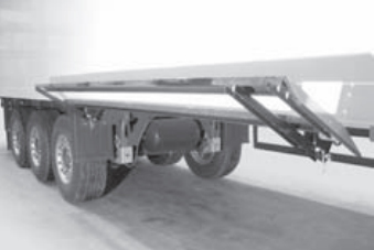
Stroke Limit ;
The shock absorbers act as stroke limiters, therefore cables or other types of stroke limit are not required.
To lower the air suspension completely a stop is mounted on the axle ties.
The stop allows the semitrailer to be driven a short distance at low speed without air on the bumper to the nearest workshop if the air suspension system fails. However, make sure that the tyres rotate freely.
Lift/lower valve ;
Use the up/down valve
· for height adjustment while loading and unloading,
· before uncoupling,
· during ferry transport,
· during intermodal transport.
Always set the up/down valve to driving position before starting a trip.
Driving with the up and down valve set to "Heben" (Up) or "Senken" (Down) may damage the load, the semitrailer, the brake and the air suspension system and will overload and destroy the shock absorber.
The up and down valve (1) has a safety function, the "dead man's switch".
This safety function ensures that when the selector lever (2) is released the spring bellows are not supplied with air or vented and the lift and lower process is stopped immediately.
In the lock position "UP" or "DOWN" the selector lever locks. The lift and lower process is not interrupted when the selector level is released.
The RtR function(Auto-Reset) is effective also in the lock positions.
The selector lever (2) has the following positions:
"FAHRT" (DRIVE) position"
The selector lever (2) is pulled out in the centre position and cannot be moved.
"STOP" position Leave the selector lever in "STOP" position or lock position "DOWN" to leave the semitrailer lowered (e.g. on the ferry) or lifted (e.g. on a ramp)

Press selector lever in from "DRIVE" position.
· It can now be moved.
To restore the driving position pull the selector lever (2) out from the "STOP" position to the "FAHRT" (DRIVE) position
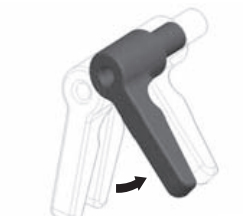
"HEBEN" (UP) position
Move selector lever (2) to the right from the "STOP" position (anticlockwise).
· The semitrailer is lifted while you hold the selector lever. When the selector lever is released it automatically returns to the "STOP" position and the lift procedure is stopped.
AXLE LIFTING SYSTEM
The lift axle automatic device can be switched off by a switch mounted on the vehicle as standard
Axle lift with ABS/EBS
In older vehicles with ABS the lift axle remains lifted when the ignition in the tractor is switched off. In newer vehicles with EBS the lift axle is lowered when the ignition in the tractor is switched off regardless of the load status. Lower the lift axle when you park the semitrailer unsupervised. In the event of air loss the axle will lower uncontrollably.
Axle loads : The lift axle lowers only when the axle on the floor exceeds the approved axle load. Depending on the load distribution the vehicle may be driven with the axle lifted with payloads up to 18 t.
The lift axle may crush feet when lowered quickly. X Switch off the axle lift before loading the semitrailer quickly with a high tonnage (e.g. coils)
LANDING LEG;
The semitrailer may cant over and cause personal injury.
· Before uncoupling make sure that the semitrailer is loaded so it will not tip.
· Load the uncoupled semitrailer so it will not tip during loading.
· Do not exceed the maximum approved support load of the landing legs
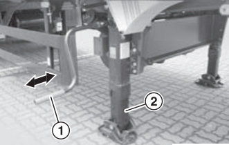
1 - Crank
2 - Support Leg
The landing leg supports the uncoupled semitrailer and adjusts the height while coupling and uncoupling. The landing leg has a high speed and a low speed mode
The landing leg can be damaged by overloading if you attempt to lift or lower the semitrailer at high speed.
· Use the landing leg in low speed only after setting the support foot on the ground; whether the semitrailer is empty or loaded.
· Switch to high speed only after the foot is lifted and relieved of all load.
Lowering support foot
· Remove crank (1) from retainer.
· Set high speed by pulling the crank out.
· Lower landing leg (2) until it touches the ground.
· Set low speed by pushing the crank in.
· Extend support foot (2) to desired length and attach crank (1).
Retracting support foot
· Remove crank (1) from retainer.
· Set low speed by pushing the crank in.
· Lift foot (2) until it no longer touches the ground.
· Set high speed by pulling the crank out.
· Retract support foot (2) completely and place crank (1) in the retainer
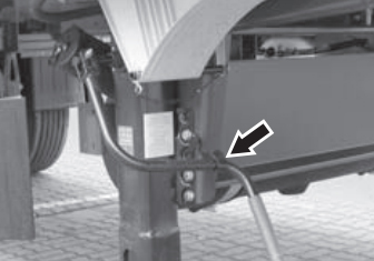
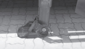
Crank retainer on the landing leg Pivoted foot
As the air suspension loses pressure the semitrailer lowers and simultaneously moves forwards (when the air suspension is lifted it moves forwards). Landing legs with length compensation (pivoted foot) compensate for these movements and protect the landing leg from deformation. Pivoted feet can move approximately 20 cm forward and back.
WHEEL CHOCKS;
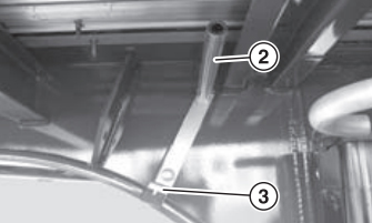
1 - Spring clip
2 - Pipe
3 - Retainer bracket
Removing wheel chock
· Pull out spring clip (1).
· Pull wheel chock out against the resistance of the retaining bracket
Stowing wheel chock
· Place wheel chock on the pipe (2).
· Slide wheel chock back until it clicks into place against the resistance of the retaining bracket
· Lock wheel chock with the spring clip (1).
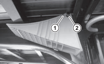
SIDE PROTECTION
Lifting
Turn locks about 90° against the resistance and pull them out
The guard can fall down and injure persons kneeling underneath it.
· Secure the raised sideguard with the lock.
Lowering (driving position)
Lower in reverse order. Rotate both locks until they snap in. Always lower the sideguard and lock it before driving.
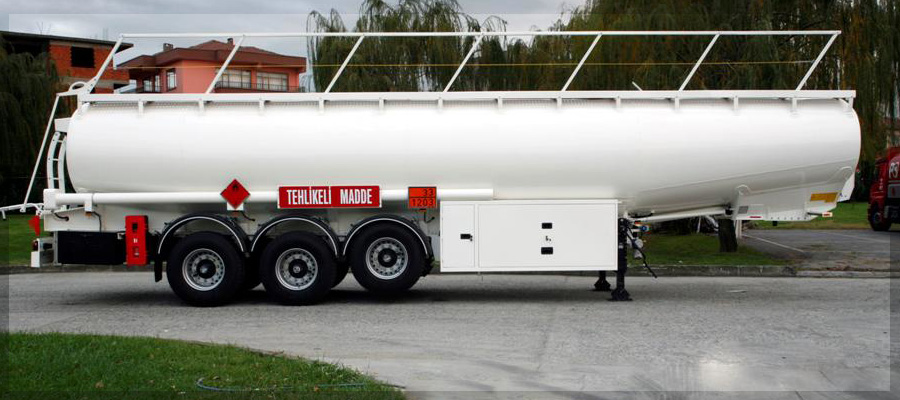
For special semi trailers like extendable trailers, bulk cement trailer, tanker trailers please click here to get user's manual
 O-Sense